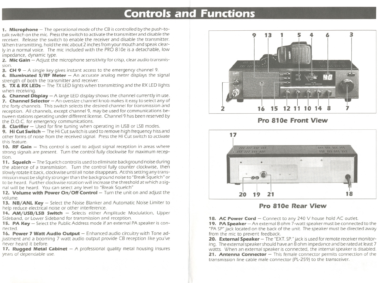
1. Microphone - The operational mode of the CBiscontrolled by the push-to-
talk switch on the mic. Pressthe switch to activate the transmitter and disable the
receiver. Release the switch to enable the receiver and disable the transmitter.
When transmitting, hold the micabout 2 inches fromyour mouth and speak clear-
ly in a normal voice. The mic included with the PRO 81Oe is a detachable, Iow
impedance, dynamic type.
2. Mic Gain - Adjust the microphone sensitivity for crisp, clear audio transmis-
sion.
3. CH 9 -- A single key gives instant access to the emergency channel 9.
4. Illuminated S/RF Meter - An accurate analog meter displays the signal
strength of both the transmitter and receiver.
5. TX & RXLEDs- The TXLEDlights when transmitting and the RXLEDlights
when receiving.
6. Channel Display - A large LEDdisplay shows the channel currently in use.
7. Channel Selector - An oversize channel knob makes it easy to select any of
the forty channels. This switch selects the desired channel for transmission and
reception. All channels, except channel 9, may be used for communications be-
tween stations operating under different license. Channel 9 has been reseNed by
the D.O.C for emergency communications.
8. Clarifier - Used for fine tuning when operating in USBor LSBmodes.
9. Hi Cut Switch - The Hi Cut switch is used to remove high frequency hiss and
other formsof noise from the receivedsignal. Pressthe HiCut switch to activate
this feature.
10. RF Gain - This control is used to adjust signal reception in areas where
strong signals are present. Turn the control fullyclockwise for maximum recep-
tion.
11. Squelch - The Squelch control isused to eliminate background noise during
the absence of a transmission. Turn the control fully counter clockwise, then
slowly rotate it back, clockwise until all noise disappears. At this setting any trans-
mission must be slightlystronger than the background noise to "BreakSquelch" or
to be heard. Further clockwise rotation will increase the threshold at which a sig-
nal will be heard. You can select any level to "Break Squelch"
12. Volume with Power On/Off Control - Turn the unit on and adjust the
volume.
13. NB/ ANL Key - Select the Noise Blanker and Automatic Noise Limiter to
help reduce electrical noise or other interference.
14. AM/USB/LSB Switch - Selects either Amplitude Modulation, Upper
Sideband, or Lower Sideband for transmission and reception.
15. PA Key - Select the Public Address mode ifan external PAspeaker is con-
nected.
16. Power 7 Watt Audio Output - Enhanced audio circuitry with Tone ad-
justment and a booming 7 watt audio output provide CB reception likeyou've
never heard it before.
17. Rugged Metal Cabinet - A professional quality metal housing insures
years of dependable use.
9 13
1 5 4
6
3
16
15
12 11 10 14
2
Pro 810e Front View
17
20
21
19
Pro 810e Rear View
11
18. AC Power Cord - Connect to any 240 V house hold AC outlet.
19. PA Speaker - An external 8 ohm 7-watt speaker must be connected to the
"PASP"jack located on the back of the unit. The speaker must be directed away
from the mic to prevent feedback.
20. External Speaker - The "EXT.SP."jack isused for remote receiver monitor-
ing. The external speaker should have an 8 ohm impedance and be rated at least 7
watts. When an external speaker is connected, the internal speaker is disabled.
21. Antenna Connector - This female connector permits connection of the
transmission line cable male connector (PL-259)to the transceiver.
~I
 (12 pages)
 Manymanuals.com
 Manymanuals.de
 Manymanuals.fr
 Manymanuals.it
 Manymanuals.pl
 Manymanuals.cz
 Manymanuals.es
 Manymanuals-pt.com
Comments to this Manuals